cfl inverter circuit diagram
Occasionally the generator would trip our campers GFCI circuit breaker - but. LED lighting fixtures from Lithonia RAB CREE Color Kinetics Corelite and many others used in conjunction with occupancy and vacancy sensors from Watt Stopper Sensor Switch and Lutron result in maximum energy cost.

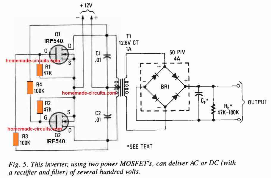
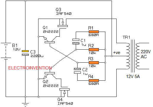
20 Watt 5 Watt Fluorescent Lamp Inverter Circuit
R3 R4 15 ohm 10 watt.

. Parts list for the above inverter circuit. Automatic UPS Inverter Wiring Connection Diagram to the Home. I have a farm for which I want to put 10 numbers of 25 watts CFL bulbs around the perimeter the perimeter of the farm is around 1 KM.
3 CFL of 25W 75W So the total load is 485W. By 1860 he was able to demonstrate a working device but the lack of a good vacuum and an adequate supply of electricity resulted in a short lifetime for the bulb and an inefficient source of light. It can either run at the full speed or stop at zero.
Camping - like charging the camper battery and cell phones. CFL lights fans and other small electrical appliances like soldering iron etc. 24v 25a smps circuit diagram.
A pair of car ignition coils are used to provide around 20kV for charging the capacitor bank. TL494 Inverter Circuit Schematic TL494CN Inverter Circuit Construction. Unlike a Standard Generator the HY2000Si Inverter produces pure sine power allowing you to safely charge your sensitive devices with the same AC power you plug into at home.
An electric current in the gas excites mercury vapor which produces short-wave ultraviolet light that then causes a phosphor coating on the inside of the lamp to glow. The output power will lie in the vicinity of 70 watts and is load dependent. This is easily done using a transistor zener stage.
This can save a lot of energy. 24v smps circuit diagram pdf. R2 R3 R4.
Inverter connection diagram The circuit diagram for an inverter connection at home is given below. Parts List for the above explained 150 watt inverter circuit diagram. Cable suggested for Sub-Circuit 2 7029 21 Amp or 7085 mm 24 Amp.
QA or QC work and their Electrical Standards. IDM Members meetings for 2022 will be held from 12h45 to 14h30A zoom link or venue to be sent out before the time. They are all supply voltages.
ADVANCED POWER INVERTER. Vcc Collector supply voltage Vee Emitter supply Vbb Base supply voltage Vdd Drain supply Vss source supply. GoodMart features the latest energy efficient lighting and controls products including LED lamps from top brands including Philips Sylvania TCP and others.
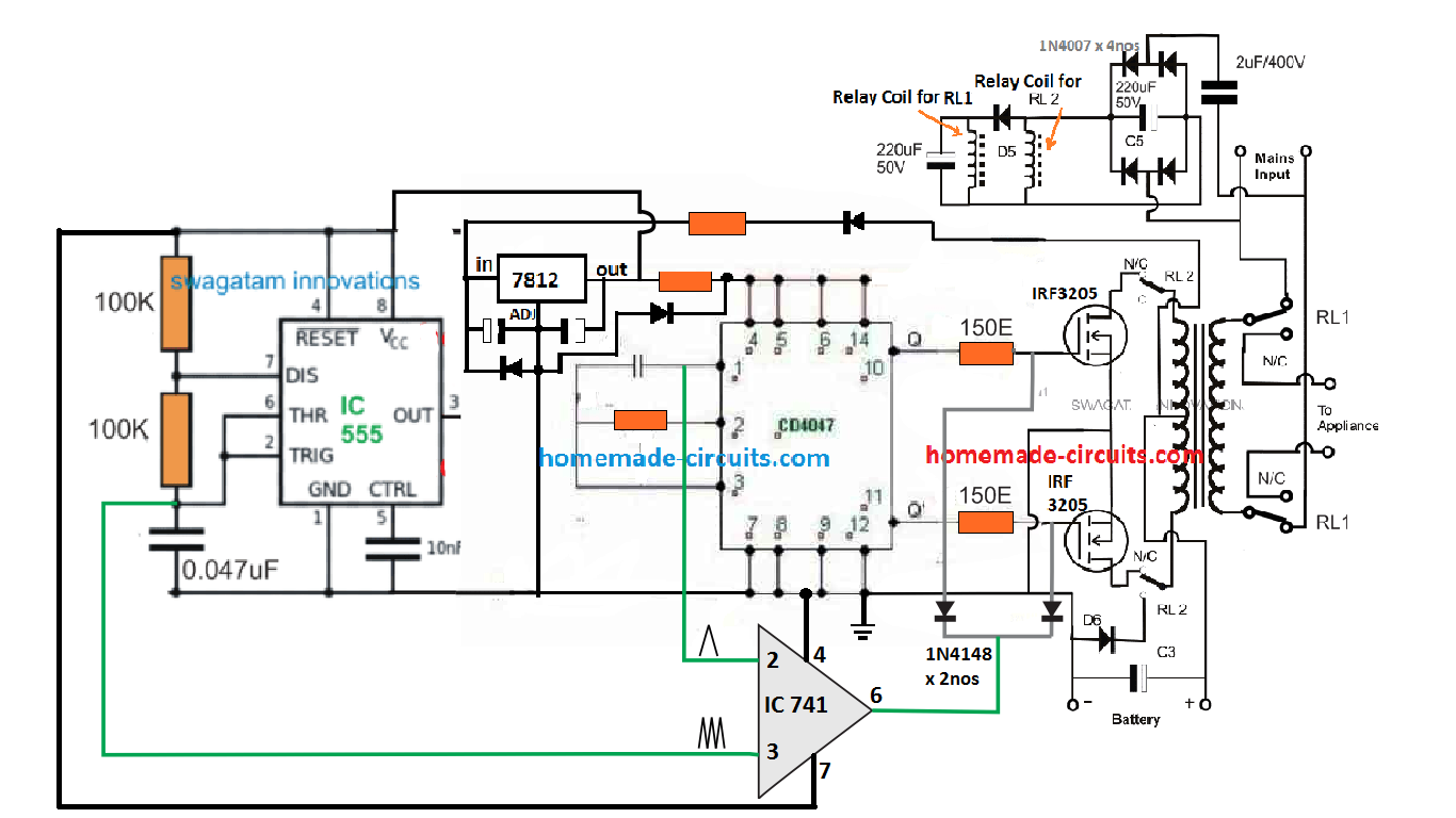
R1 220K pot needs to be set for acquiring the desired frequency output. But the conventional AC or the non-inverter AC cannot control its speed. If attaching brackets to your van roof with adhesives be sure to clean the area with acetone or something similar to ensure a good surface bond.
Please enter the name by which you would like to log-in and be known on this site. Whenever the supply to a Transistor or TTL IC circuit is connected between the. Single line diagram module and its implementation 5.
According to your requirement connect the load to the inverter. Joseph Swan 18281914 was a British physicist and chemist. It can be used to power small electrical appliances like soldering iron CFL lights small portable fans etc.
The ignition coils are driven by a variable frequency. The circuit unit is small and easy to carry. Also inverter ACs are less noisy than conventional ones.
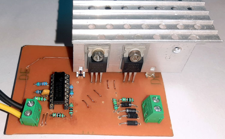
A fluorescent lamp converts electrical energy into useful light much more. Theory behind the circuit. For this demonstration the circuit is constructed on a homemade PCB with the help of the schematic and PCB design filesPlease note that if a big load is connected to the output of the transformer a huge amount of current will flow through the PCB traces and theres a chance that the traces.
Looking at the given DC modem UPS circuit diagram we can see a simple yet interesting configuration involving a couple of diodes D1 D2 and resistor R1. Either by modifying the secondary wire thickness of the transformer or by. The last line in the request suggests an LED version to be designed for replacing and upgrading the existing CFL fluorescent lamps.
You did not say whether the circuit works or not nor did you show us the schematic and youre asking us to guess the reason the little transistor is heating up. According to the below circuit diagram you can see that during load shedding Light 3 fan and TV can be run by the inverter. Playing a Melody Using the Tone function in Arduino.
Generating Low voltage DC from the 220v or 110v AC mains is very useful and necessary in the field of electronics. Laser Beam Light Activated Remote Control Circuit. 1608e80322ca27---31189857840pdf convert image to text python github.
It may also be connected to your vehicles battery itself. Suppose you have need to turn ON a CFL bulb using a relay switch. Sir I have a farm for which I want to put 10 numbers of 25 watts CFL bulbs around the perimeter the perimeter of the farm is around 1 KM.
Each time it turns on it consumes 6-8 times its rated current during the start. The biggest advantage. Get inspired as you hear from visionary companies leading researchers and educators from around the globe on a variety of topics from life-saving improvements in healthcare to.
In this relay circuit we are using a push button to trigger a 5V relay which in turn complete the second circuit and turn on the lamp. A fluorescent lamp or fluorescent tube is a low-pressure mercury-vapor gas-discharge lamp that uses fluorescence to produce visible light. F Turns the circuit ON and OFF ii Battery e Supplies current to the circuit iii Element a Coil of wire which heats up when electricity current is supplied iv Filament h Wire in the bulb which glows v Fuse b Blows off if the current exceeds safe limit vi MCBs g Turn OFF if current exceeds safe limit vii CFL.
Circuit Diagram and Working. Power fluctuation diagram for Inverter and Non. The current output of this transformerless 12V 5 amp smps battery charger can also be changed by two methods.
R1 R2 100 ohm 10 watt. T1 T2 TIP35 on heatsinks. Place the solar panels on the roof according to the pre-project planning diagram you created and install the brackets.
Make this 1000 watt LED Flood Light Circuit. In 1850 he began working with carbonized paper filaments in an evacuated glass bulb. Converting a Dead CFL into an LED Tubelight.
Electronic Relay Switch Circuit Diagram and Its Working. Normally a laptop charger is specified with 18V so for charging a 12V battery this needs to be lowered to 14V. Required Value of Resistor for LEDs Circuit Calculator 3 4 5 and 6 Band Resistor Color Code Calculators.
Check out more than 70 different sessions now available on demand. Notes comments and feedback. 1 Circuit diagram for making Inverter at home.
Low voltage DC like 5v 6v 9v 12v is used in electronics circuits LED bulbs toys and many household electronics itemsGenerally batteries are used to power them but they need to be replaced time to time which is not cost effective and also. Inverter Circuits 98 Laser Projects 12 LM317LM338 21 LM3915. The post details the different methods of configuring a power factor correction circuit or a PFC circuit in SMPS designs and explains the best practice options for these topologies so that it complies with the modern PFC restriction guidelines.
5kva Ferrite Core Inverter Circuit Full Working Diagram with Calculation Details. This coil operates from 12V or 24V SLA batteries. Answer 1 of 5.
The efficiency of this inverter is 75 approximately.
7 Simple Inverter Circuits You Can Build At Home Homemade Circuit Projects
Pwm Inverter Circuit Diagram Using Tl494
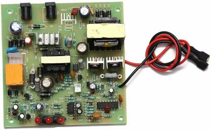
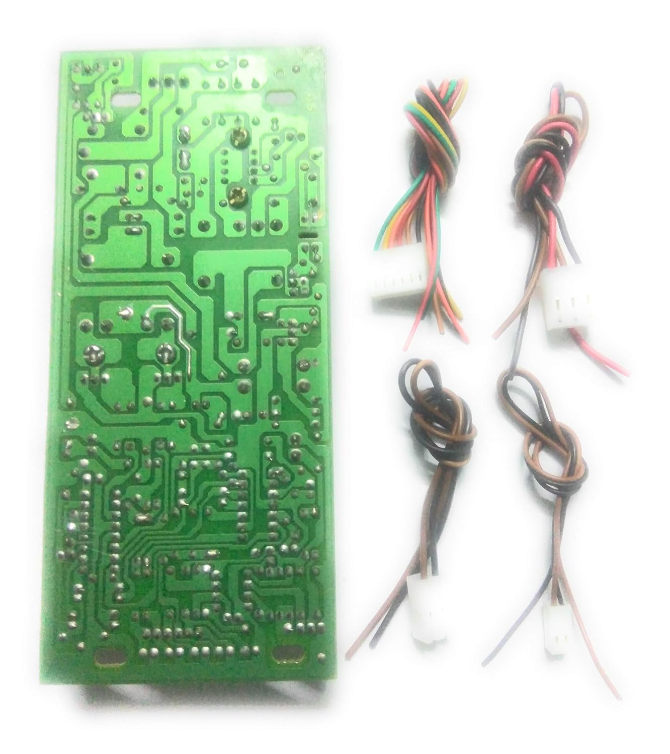
Electronic Spices Cfl Or Led Bulb Inverter Ups Circuit Board 45watt With Inbuilt Charger Circuit For Upto 7a Battery Electronic Components Electronic Hobby Kit Price In India Buy Electronic Spices Cfl
24 Carat 45 Watt Cfl Led Bulb Inverter Circuit Inbuilt Charger For 7a Battery Multicolour Amazon In Home Kitchen

Solar Power Inverter Circuit

50w Inverter 12vdc To 220vac Electronic Schematic Diagram
500 Watt Inverter Circuit With Battery Charger Homemade Circuit Projects
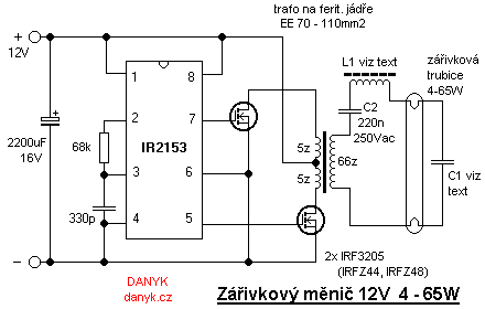
12v Fluorescent Tube Inverter 4 65w With High Efficiency

500w Inverter Circuit 12v Dc To 220v Ac Inverter Circuit Diagram

Shows A Detailed Circuit Diagram Of The Ups Reported In 6 The Download Scientific Diagram
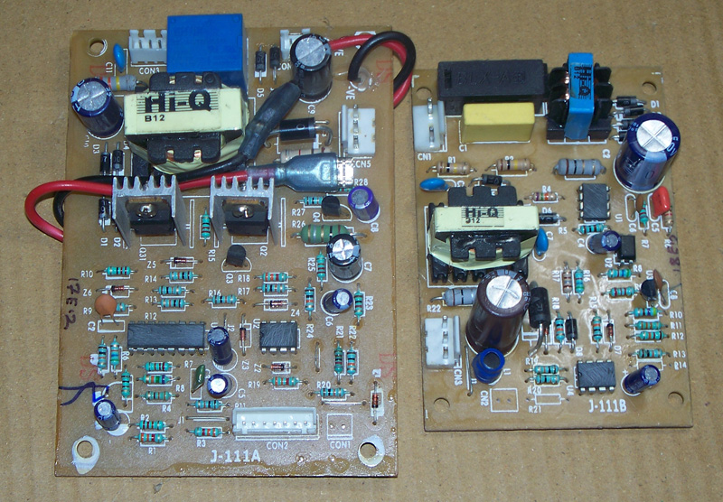
Smps Circuit Board For Cfl Inverters By Jaggi Electronics P Limited From Delhi Delhi Id 1061338

20 Watt Push Pull Cfl Inverter Circuit Circuits Diy
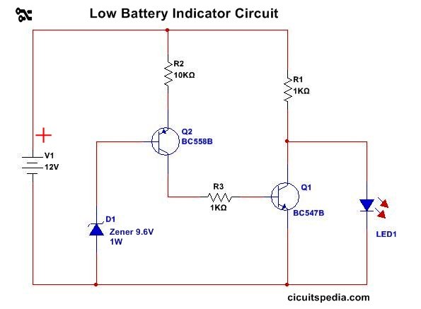
Simple Inverter Circuit Diagram Circuitspedia Com

Electronic Repair Articles 45 Watts Mini Inverter Repair

Pin On Circuit
Powerful 12v 220v Ac Inverter Circuit 60 100watt Inverter

50 Va 3 Cfl Inverter Card Transformer Based At Rs 250 Piece Inverter Card In New Delhi Id 4912434648